
How to Choose a Digital Signal Isolator for Your Application?
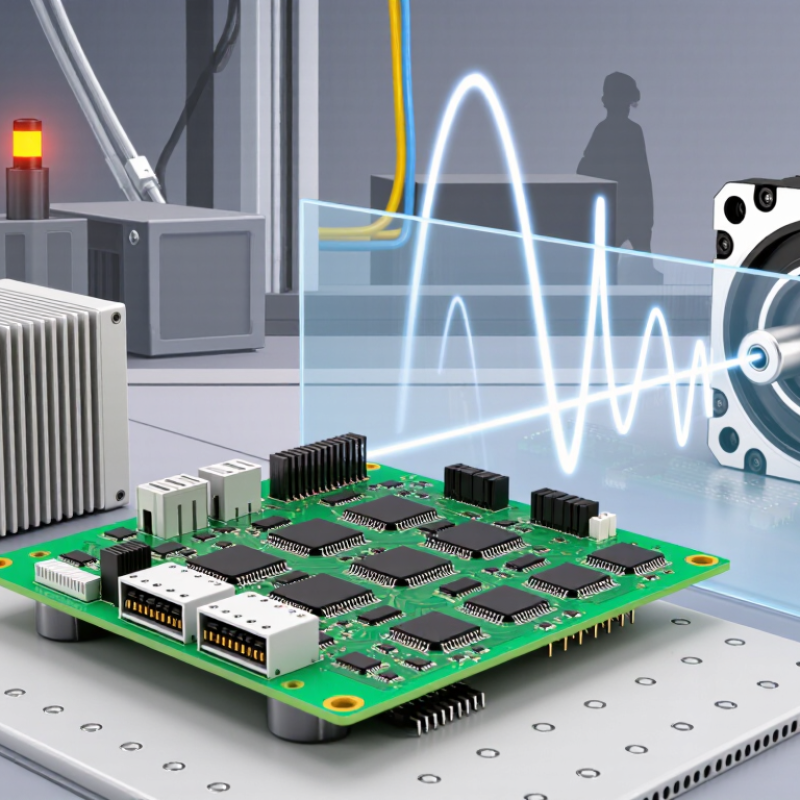
Choosing a Digital Signal Isolator is not just a matter of matching logic levels. The device must keep signals moving while limiting hazardous energy across an isolation barrier. A small control board beside a motor drive may face fast voltage transients, noisy switching edges, and limited PCB space. The right choice depends on the whole system, not a single headline specification.
The Semiconductor Industry Association, citing WSTS data, reported global semiconductor sales of $627.6 billion in 2024, up 19.1% from 2023. That figure describes the broader chip market, not digital isolators alone. Still, it reflects the expanding electronics landscape in which isolation supports industrial automation, energy systems, and connected equipment. The details matter. For practical selection, compare working voltage, surge withstand, common-mode transient immunity, channel count, data rate, power use, package layout, and applicable safety certifications. A strong isolation rating cannot compensate for poor PCB spacing or unsuitable system-level protection.
Texas Instruments isolation expert Thomas Kugelstadt has published design guidance on digital isolators. A cautious paraphrase of its core lesson is: “Choose the isolation barrier for the system’s voltage and safety needs, then verify signal performance.” Treat that as a design principle, not a verbatim quotation. Engineers should also check datasheets and certification documents for the exact operating conditions behind each rating. A device may pass a bench test and still behave differently near a switching inverter. That is an easy detail to overlook. This guide will help compare the trade-offs, identify application requirements, and avoid choosing a part from one attractive specification alone.
Identify the Application’s Signal, Voltage, and Isolation Requirements
How to Choose a Digital Signal Isolator for Your Application?
Identify the Application’s Signal, Voltage, and Isolation Requirements
Start at the pins. Identify whether the circuit carries SPI, UART, PWM, or another digital signal. Note the logic levels on both sides, such as 3.3 V and 5 V, and check whether the signal is unidirectional or bidirectional. A compatible logic threshold matters; a clean-looking waveform can still fail if the receiving input does not recognize its voltage as high.
Next, estimate the required data rate and timing margin. Fast edges and long cables can introduce ringing, while propagation delay may affect a tightly timed interface. Check the isolator’s channel count and direction to match the signals you actually need. Avoid choosing by headline data rate alone. The real system includes traces, connectors, and input capacitance.
Isolation requirements deserve equal care. Compare the working voltage with the expected voltage difference during normal operation, then review transient withstand and common-mode transient immunity for switching events. Also consider package spacing, board layout, and the environment around the device. A small enclosure near a motor drive may face different noise and temperature conditions than a quiet sensor board. A datasheet cannot describe every installation. Record assumptions, verify them against the actual circuit, and leave margin where measurements are uncertain.
How to Choose a Digital Signal Isolator for Your Application? — Identify the Application’s Signal, Voltage, and Isolation Requirements
| Application | Signal and Typical Data Rate | Logic-Side Voltage | Isolation Requirement to Define | Selection Considerations |
|---|---|---|---|---|
| Microcontroller-to-peripheral SPI | Clock, data, and chip-select; commonly 1–10 MHz, with faster designs requiring additional timing checks | Often 3.3 V on one or both sides; some systems use 1.8 V or 5 V | Set the required working voltage from the system’s operating voltage, insulation category, pollution degree, and applicable safety standard | Choose enough channels in the required directions. Check propagation delay, channel-to-channel skew, and maximum data rate against the SPI timing budget. |
| UART between control boards | TX and RX; commonly 9.6 kbit/s to 1 Mbit/s | Typically 3.3 V or 5 V; confirm each side’s input thresholds | Define the maximum continuous working voltage and required transient withstand based on the two circuit domains | Use channels in opposite directions for full-duplex communication. Include any enable or handshake signals that also cross the isolation barrier. |
| I²C between isolated circuit sections | Open-drain clock and data; Standard-mode 100 kbit/s, Fast-mode 400 kbit/s, or Fast-mode Plus 1 Mbit/s | Commonly 3.3 V; pull-up voltage may differ between the two sides | Specify the required working voltage and insulation level for the complete isolation barrier | Check that the solution supports bidirectional open-drain signaling. Account for pull-up resistors, bus capacitance, rise time, and low-level voltage limits. |
| Industrial controller input or output | On/off status or control signal; typically static or low frequency, with application-specific switching rates | Field wiring may be 24 V, while the isolator logic side is typically 3.3 V or 5 V | Determine the field-side working voltage, surge environment, and required protection level from the installation conditions | A 24 V field signal generally needs suitable input conditioning, such as a resistor network or interface circuit, before a logic-level isolator. Check fault and transient protection. |
| PWM control or gate-driver command | PWM or enable signals; often from a few hundred hertz to tens or hundreds of kilohertz | Logic input may be 3.3 V or 5 V; the isolated output supply may be separate | Set working-voltage, transient, and insulation requirements from the power-stage design and applicable safety standards | Check propagation delay, pulse-width distortion, minimum pulse width, and common-mode transient immunity. A digital isolator does not by itself provide isolated power. |
| Isolated RS-485 or CAN interface | Differential bus signaling; data rate depends on the protocol, cable length, and network design | Logic side commonly uses 3.3 V or 5 V; bus-side supply requirements depend on the transceiver | Define isolation requirements for the complete interface, including the bus transceiver and power supply | Use an isolated bus transceiver or a digital isolator paired with a suitable transceiver. Consider isolated bus-side power, termination, grounding, and surge protection. |
| Isolated fault or status feedback | Single digital status line; usually static or low frequency | Often 3.3 V or 5 V on the receiving side | Choose the working-voltage rating for the voltage continuously present across the barrier; verify transient and safety requirements separately | Check default output state, power-up behavior, channel direction, and whether the required fail-safe behavior is achieved when either side loses power. |
Design note: The rates and logic voltages shown are common examples, not device specifications. Select an isolator using the actual signal timing and voltage ranges, and distinguish continuous working voltage from short-duration withstand or test voltage. Confirm isolation and creepage requirements against the applicable system safety standard.


